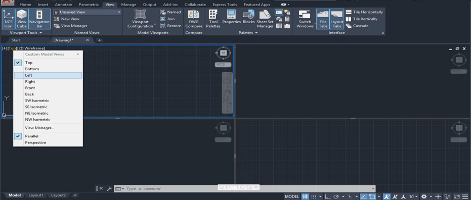

When you print the viewport to PDF (or similar), the lines should be nice vectors you can work with in Illustrator. Set the Visual style of the viewport to 2D wireframe.Enter the dispsilh command, press enter and set the value to 1 (this removes the facet edges when the hide command is given).Use this procedure to be able to export or print is in vector format: Here we can learn how we change mv viewport in layout so it's very simple just two steps to rotate with DVIEW COMMAND. But this will automatically export the viewport as a bitmap image and not vectors. If you have a 3D solid model that you want a line drawing of with the hidden lines removed, you could set the display mode to 3D Hidden. Make sure that the VPROTATEASSOC system variable is set to 1. Make sure that you are in paper space by double-clicking outside any layout viewports. In the Page Setup dialog, click the Edit button next to the list where the Plot style table is selected:įor each color you can view or edit the settings, such as: print color, line weight, etc.Įxporting/Printing 3D viewports with hidden lines as Vector drawings To Rotate a View Within a Viewport Click the layout tab in which you want to rotate a view. Go to View > Viewports > Object and select the closed line to be turned into a viewport. Use the Close option when drawing a polyline to make sure it's closed. I also have a lisp routine on my website that.

Inside the viewport use the DVIEW command, select some of your drawing, then use the TWIST option to rotate your view. You can draw any shape you want to be used as a viewport. There are a couple of ways to do this: Inside the viewport use the UCS command to rotate your ucs about the z axis, then use the PLAN command to align your view to the new ucs. The model space within the viewport will now be rotated so as to align the viewports UCS with the paperspace UCS. Select Current UCS (default) and press enter.

The UCS is now rotated within the viewport. Enter the rotation in degrees (counter clockwise). Click inside a viewport to apply the rotation to that. Pick 2 points in Paper space to define the desired angle. Pick 2 points within the viewport that define the angle. Found on the Express Tools tab > Layout panel > Align Space tool. Users should have a high degree of proficiency in AutoCAD before using any of these methods. Choose Rotate Z from the UCS toolbar, or use the command ucs, z. Activate the viewport in which the view is to be rotated. In this case the roadway drawing entities are not rotated.To rotate the model space within one of the viewports, the following steps must be taken: It might be convenient to activate the USC toolbar: RMB-click on an empty part of you toolbar space, choose ACAD > UCS. Although you can define a non-world UCS in paper space, the view remains in plan view to the world coordinate system.We're using a number of UCS-related functions. The setting of UCSFOLLOW is maintained separately for paper space and model space and can be accessed in either, but the setting is ignored while in paper space (it is always treated as if set to 0).

Your UCS should aligh with your line (make sure its on). It will change to a plan view again the next time you change coordinate systems.ġ Any UCS change causes a change to the plan view of the new UCS in the current viewport AutoCAD: How can I rotate a drawing inside viewport without Type UCS, then E for Entity (you can also use O for object) and select your line. Once the new UCS has been established, you can use DVIEW, PLAN, VIEW, or VPOINT to change the view of the drawing. If UCSFOLLOW is on for a particular viewport, AutoCAD generates a plan view in that viewport whenever you change coordinate systems. Set UCSFOLLOW separately for each viewport. Generates a plan view whenever you change from one UCS to another. *possibly* it's the UCSFOLLOW variable, which is set from within each viewport.


 0 kommentar(er)
